Front panel backlight LED mod
By Jon P. Zaimes, AA1K
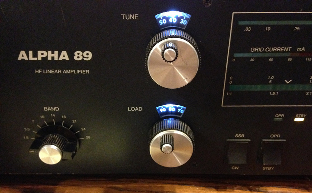
The original incandescent bulbs that backlit the Tune and Load dials in my Alpha 89 amplifier expired several years ago, and I had replaced them with a couple of small spare incandescent bulbs for a TS940S that I happened to have on hand. Recently one of these expired so I decided it was time to upgrade with LEDs so I’d likely never have to replace them again. These dials are extremely difficult to read without the backlights.
This project coincided with a periodic cleaning of the inside of the amplifier. I had been tardy in doing this annual (or sooner) maintenance, and the accumulation of dust was causing the amplifier to frequently hard-fault to off. The last time it did this with quite a bang, and while I feared some component had cooked, none could be found but there was a lot of dust found inside. Careful work with a vacuum, and a final blow-out of hard to reach spots with compressed air, restored the amp to cleanliness and normal operation.
The bulbs are accessed by removing the Tune, Load and Band knobs, and then the six screws that hold the front panel to the cabinet. The panel then slides directly forward off of the three control shafts. Make sure the amp is unplugged – the wires attaching to the switches could easily short to the chassis during removal.
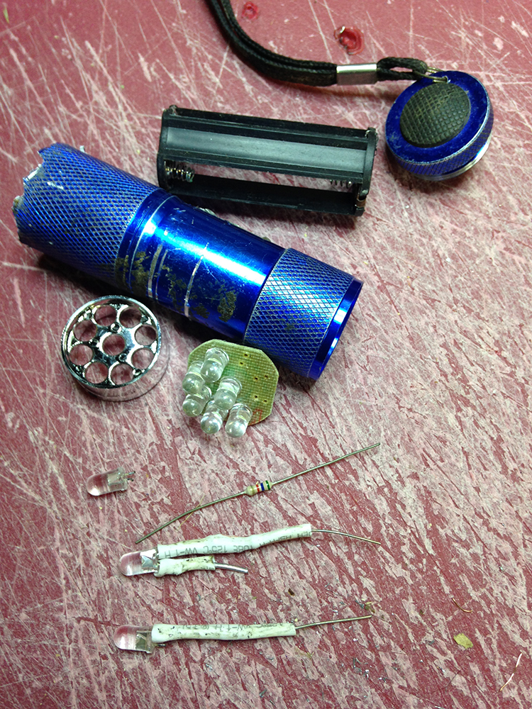
I didn’t have any white LEDs on hand, but did have an old Harbor Freight LED flashlight – one of the cheap ones that they often give away. It had been on the boat and the battery holder corroded, but I kept it around for parts. I carefully cut it open and unsoldered two of the LEDs from their small circuit board.
The original bulbs were not shown on the schematic in my manual, nor was the bulb type listed. In fact when I had previously contacted Alpha about replacements they told me there were two different types that had been used in production. So I had no clue what the supplied voltage was to these sockets.
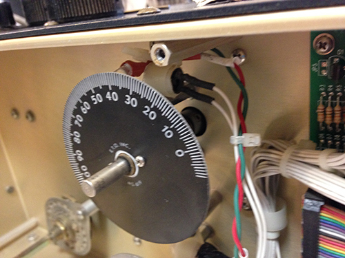
I connected two wires to these sockets and extended them through the front panel, which I temporarily reattached so the switches didn’t short to the chassis when I powered up the amp. The voltage turned out to be 12.6 VDC, and I noted the polarity.
I installed a 5.6K ohm ¼ watt resistor in series with the positive lead of each LED to drop the supplied voltage to what was needed, and used some shrink tubing to insulate the resistor as well as a wire connected to the other terminal. A larger piece of shrink wrap was then placed over the whole assembly, wires spliced into the original lamp wiring were spliced in and shrink-wrapped, and wire ties were then used to attach the new LED assemblies to the existing lamp socket with the LED shining directly behind the dial.
I found a single LED behind each was sufficient, but additional ones could be used for more brightness.
UPDATE: In January, 2019, I purchased a second used Alpha 89. This one was manufactured in 1993 – three years before the one modified previously. The voltage going to the pilot lights in this one measured 29 VDC. I used the same dropping resistor as in the original mod. The bulbs used also were surplus from a Harbor Freight flashlight. These are thus much brighter than in the original (1996 Alpha 89) mod. The components run cool so I’m leaving it that way.
NOTES: I determined the polarity of my LEDs by hooking up temporarily to two 1.5 volt batteries in series. The smaller electrode visible inside the LED was the positive terminal in the ones I used.
On my 1993 model Alpha 89, the 2-pin connector for the original voltage supply on the large PC board behind the front panel had the positive 29 VDC on the bottom terminal.
UPDATED (11/25/2019): Just before the CQ WW DX SSB contest last month I discovered that Alpha 89 No. 1 was deaf on receive. But when I switched it to “standby” the receiver came to life. A quick look at the schematic found that the the standby switch controlled a relay that bypassed the pin diode switching. So the diodes were likely the problem. While I have done a few repairs on the 89 I purchased used in 2007, I decided to seek professional help on this one. I emailed two providers in Colorado and never did hear back from them. But Dick Byrd, N4UQ, who specializes in repairs and updates on older Alphas, got back to me in about three days and apologized for the delayed response because he had been on vacation! His promised one-week turnaround was true, he corresponded with me as the repairs progressed (he replaced the receive pin diodes and also replaced the front panel rocker switches that sometimes wouldn’t allow the amp to be switched off) and I had the amp back in time for CQ WW CW. It worked great all through the contest (44+ hours). The repair cost was very reasonable and I will be sending 89 No. 2 to Dick next to repair a new problem with it (stops transmitting and the “wait” light comes on.) He has his own transformer so I didn’t need to ship that, saving cost. Three weeks later, I still haven’t heard from the other two providers.
A version of this original article appeared in the GOFRC bulletin of the Frankford Radio Club.